Overview
Many Zebra scanner devices support active monitoring of device performance over time. Such statistical data is collected and stored locally on each device. This data can be retrieved with directives from Zebra's IoT Connector utility or by sending CoreScanner API commands to the scanner device using the Scanner SDK Sample Application for example.
When a notification of a critical change to a scanner device is needed, a feature called “Real Time Alerts” can be used to transmit alerts from the scanner or cradle to a host when certain requested statistic values change, or events occur.
Real Time Alerts (RTA) are a selection of events that are monitored by a scanner device. When a selected statistic has reached a specified value or when a selected event occurs, it is then reported by the scanner device to the host as an Alert.
The scanner device and its installed firmware must support RTA monitoring, and the data or feature being monitored must be enabled on the device before an alert can be registered.
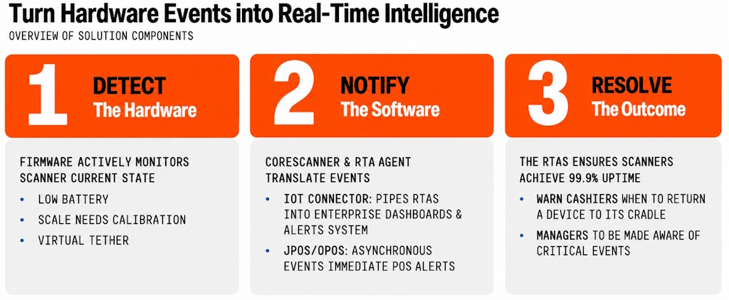 Figure 1: Real Time Alerts Overview
Overview
Each scanner model maintains a selection of Real Time Alerts (RTAs) that it supports, and the client's host system can configure the alerts that are of concern.
Zebra provides downloadable utilities, code libraries, interfaces and services that assist in the use of the Real Time Alert features. RTA features have been added to the following Zebra host software:
- RTA Agent is a lightweight, cross-platform, stand-alone application designed to manage RTA (Real-Time-Alert) configurations on connected Zebra scanners.
- IoT Connector is another lightweight, cross-platform, stand-alone application that processes RTA events in addition to Statistic and other event data to provide a complete solution for the customer.
- OPOS and JPOS APIs are provided with the OPOS and JPOS components of the Zebra Scanner SDK that can be used to capture RTA events via Zebra-specific DirectIO methods.
- CoreScanner service is Zebra’s background process that provides communication between connected scanners and applications.
- CoreScanner API methods support configuration and reception of event data from a device's RTA-capable firmware for application development via the Zebra CoreScanner background process.
- Bi-directional communication protocols such as Zebra’s USB-SNAPI, USB-IBM Handheld, USB-IBM Tabletop or Simple Serial Interface (SSI) are required to support RTA functionality.
Real Time Alerts must first be registered on RTA-capable devices using the RTA Agent which runs in the background on the host system. Supported RTAs are configured by the RTA Agent as defined in its configuration file RTAAgent-Config.xml. The RTA Agent monitors the host for scanner connections and when detected, configures the RTAs on the scanner as specified in the RTAAgent-Config.xml file.
When a specified RTA occurs on a scanner, it sends that RTA event to the host system where it can be collected and processed by:
- The IoT Connector which can forward the event to defined data sinks such as a cloud database, local file, network file or Windows Event log.
- An OPOS application using a Zebra-specific OPOS Direct IO events to receive notifications when an RTA event is sent by the scanner.
- A JPOS application using a Zebra-specific JPOS Direct IO events to receive notifications when an RTA event is sent by the scanner.
- A CoreScanner application using a Zebra-specific CoreScanner API notification events to receive RTA events sent by the scanner.
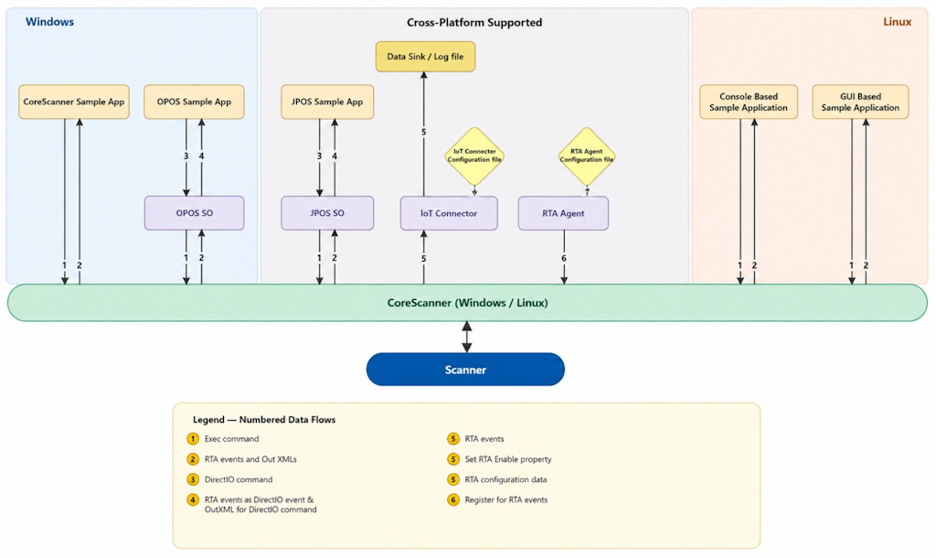 Figure 2: How Real Time Alerts Work
Example for Illustration: Out-of-Range Event Turned into Real Time Alert
- What: Enable asset management to deliver 99.9% device uptime by minimizing lost devices and enabling quicker, more precise repairs.
- Problem: RTAs trigger when your DS9908 is no longer configured properly, DS8178 scanner is misplaced, DS3678 battery needs replacement, or MP7201 scale needs calibration and much more.
- How: Using the 123Scan Software Suite, RTAs help manage your devices more efficiently.
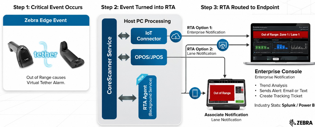 Figure 3: Out-of-Range Event Turned into a Real Time Alert
Configuration Persistence
The scanner’s RTA configuration only lives as long as the scanner remains continuously discovered by CoreScanner. If a scanner is rebooted, reconnected or power cycled, its RTA configuration is lost. The RTA Agent handles this scenario as it monitors scanner connection events and reprograms devices each time they reconnect to the host system’s CoreScanner process.
Please refer to the RTA Agent documentation.
IoT Connector
Enable RTA alerts in IoTConnector-Config.xml by setting the tag to True as shown below.
<!-- Configure RTA events - intended for collection of scanner real time alerts-->
<on-real-time-alerts enabled="true"/>
Please refer to the IoT Connector for Windows and Linux documentation to learn more about the configurations.
Real-Time Alert (RTA) Support in CoreScanner
The RTA Agent uses the CoreScanner API to configure the Real Time Alerts (RTA) feature on a scanner or cradle device. There is also a CoreScanner API call to receive notifications when an RTA event is sent by the scanner or cradle.
Real Time Alerts (RTAs) operate on a subscription-based notification system. For an application developed using the CoreScanner API to receive these alert events from a device, it must be configured to listen for the appropriate events.
Windows
The CoreScanner mechanism to receive RTA events involves two phases:
- Event Registration: An application subscribes to notifications by executing the REGISTER_FOR_EVENTS method (Opcode: 1001) and targeting the SUBSCRIBE_OTHER (Parameter ID: 32) event category.
- Alert Event Delivery: Once registered, the system automatically routes triggered Real Time Alert Events to the application. These are delivered as a specific "Notification Event" identified by RTA Event type number 2000.
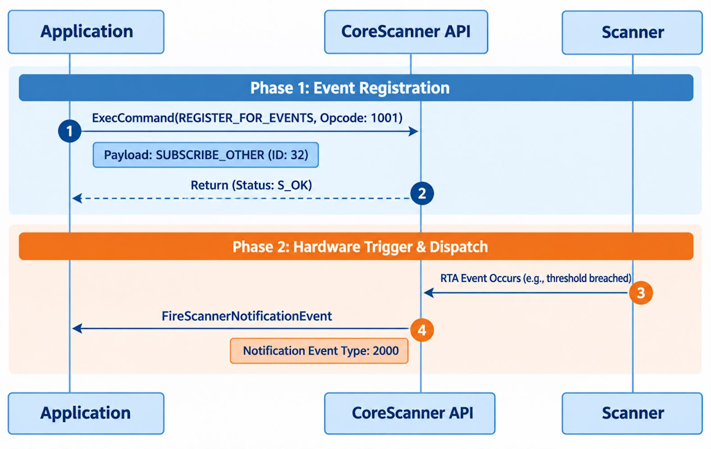 Figure 4: CoreScanner RTA Event Flow on Windows
Subscribe for RTA Scanner Notification Events on Windows (REGISTER_FOR_EVENTS)
Syntax:
C#
void ExecCommand(
     int opcode,
     ref string inXML,
     out string outXML,
     out int status);
C++
virtual /* [helpstring][id] */ HRESULT STDMETHODCALLTYPE ExecCommand(
    /* [in] */ LONG opcode,
    /* [in] */ BSTR *inXML,
    /* [out] */ BSTR *outXML,
    /* [out] */ LONG *status) = 0;
Parameters
- opcode - Method to execute.
- inXML - Relevant argument list for the opcode, structured into an XML string.
- outXML - XML string, scanner meta information.
- status - Return value for the command.
Return Values
- 0 - Success.
- Any other value - See Error and Status Codes in the Appendix.
C++
#define REGISTER_FOR_EVENTS 1001

long nRouterResult = S_OK;
long status = -1;
CComBSTR inXML = LR"(<inArgs>
                        <cmdArgs>
                            <arg-int>1</arg-int> <!-- Number of Events -->
                            <arg-int>32</arg-int> <!-- Event ID/s -->
                        </cmdArgs>
                    </inArgs>)";
CComBSTR outXML;

nRouterResult = ExecCommand(REGISTER_FOR_EVENTS, &inXML, &outXML, &status);
C#
const int REGISTER_FOR_EVENTS = 1001;
const int S_OK = 0;
long nRouterResult = S_OK;
long status = -1;
string inXML = @"<inArgs>
                    <cmdArgs>
                        <arg-int>1</arg-int> <!-- Number of Events -->
                        <arg-int>32</arg-int> <!-- Event ID/s -->
                    </cmdArgs>
                </inArgs>";
string outXML = string.Empty;

nRouterResult = ExecCommand(REGISTER_FOR_EVENTS, ref inXML, ref outXML, ref status);
Receive RTA Events through OnScannerNotification on Windows
Syntax
C#
void OnScannerNotification(
     short notificationType,
     ref string pScannerData)
C++
void OnScannerNotification(
     short notificationType,
     BSTR pScannerData)
Notification Event Types
Table 1: Notification Event Types (Windows)
| Event Type | Value | Description |
|---|---|---|
| DECODE_MODE | 1 | Trigger when a scanner changes its operation mode to decode. |
| SNAPSHOT_MODE | 2 | Trigger when a scanner changes its operation mode to image mode. |
| VIDEO_MODE | 3 | Trigger when a scanner changes its operation mode to video mode. |
| DEVICE_ENABLED | 13 | Trigger when the scanner is enabled. |
| DEVICE_DISABLED | 14 | Trigger when the scanner is disabled. |
| RTA_EVENT | 2000 | Trigger when RTA event is received. |
Sample app code snippet.
C#
const int RTA_EVENT = 2000;

void OnScannerNotification(short notificationType, ref string pScannerData)
{
    try
    {
        switch (notificationType)
        {
            case RTA_EVENT:
                UpdateResults("Scanner Notification : RTA Event Received");
                UpdateRtaEvent(pScannerData);
                break;
            .
            .
        }
    }
    catch (Exception)
    {
    }
}
Linux
The CoreScanner mechanism to receive RTA events involves two phases:
- Event Registration: An application subscribes to notifications by executing the CMD_REGISTER_FOR_EVENTS method (Opcode: 1001) and targeting the SUBSCRIBE_OTHER (Parameter ID: 32) event category.
- Alert Event Delivery: Once registered, the system automatically triggered Real Time Alert Events to the application. These are delivered as a specific "Notification Event" identified by RTA Event type number 2000.
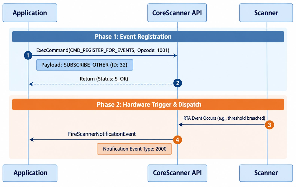 Figure 5: CoreScanner RTA Event Flow on Linux
Subscribe for RTA Scanner Notification Events on Linux (CMD_REGISTER_FOR_EVENTS)
Syntax:
unsigned short ExecCommand(
    unsigned int opcode,
    std::string inXml,
    std::string &outXml,
    StatusID *status
)
Parameters
- opcode - Method to execute.
- inXML - Relevant argument list for the opcode, structured into an XML string.
- outXML - XML string, scanner meta information.
- status - Return value for the command.
Return Values
- 0 - Success.
- Any other value - See Error and Status Codes in the Appendix.
enum CmdOpcode::CMD_REGISTER_FOR_EVENTS = 1001

StatusID status;
std::string inXml =
    "<inArgs>
       <cmdArgs>
         <arg-int>1</arg-int>
         <arg-int>32</arg-int>
       </cmdArgs>
     </inArgs>";

std::string outXml;

::ExecCommand(CMD_REGISTER_FOR_EVENTS, inXml, outXml, &status);
Receive RTA Events through OnScannerNotification on Linux
Syntax
virtual void OnScannerNotification(
    short notificationType,        // Notification event type
    std::string& pScannerData      // Notification event input/output
);
Notification Event Types
Table 2: Notification Event Types (Linux)
| Event Type | Value | Description |
|---|---|---|
| SCANNER_NOTIFICATION_UKNOWN | 0 | |
| SCANNER_NOTIFICATION_DECODE_MODE | 1 | Trigger when a scanner changes its operation mode to decode. |
| SCANNER_NOTIFICATION_SNAPSHOT_MODE | 2 | Trigger when a scanner changes its operation mode to image mode. |
| SCANNER_NOTIFICATION_VIDEO_MODE | 3 | Trigger when a scanner changes its operation mode to video mode. |
| RTA_EVENT | 2000 | Trigger when RTA event is received. |
Sample app code snippet.
const int RTA_EVENT = 2000;

Void OnScannerNotification(short notificationType, std::string& pScannerData) {

    switch ( notificationType ){

        case RTA_EVENT:
            UpdateResults("Scanner Notification : RTA Event Received");
            UpdateRtaEvent(pScannerData);
            break;

        default:
            break;
    }
}
The RTA_EVENT Message Format (Linux/Windows)
<?xml version="1.0" encoding="UTF-8"?>
<outArgs>
    <scannerID>2</scannerID>
    <arg-xml>
        <modelnumber>DS8178-SR0F007ZZWW</modelnumber>
        <serialnumber>99887766556655  </serialnumber>
        <GUID></GUID>
        <rta>
            <id>30012</id>
            <type>12</type>
            <data-1>99</data-1>
            <data-2>0</data-2>
            <raw-data>0x75 0x3C 0x00 0x0C 0x00 0x63 0x00 0x00 0x00 0x00 </raw-data>
        </rta>
    </arg-xml>
</outArgs>
- The <scannerID> tag is the CoreScanner-assigned ID number of the scanner device that originated in the RTA event.
- The <modelnumber> and <serialnumber> tags indicate the asset info of the device that originated the RTA event.
Under the <rta> tag:
- The <id> tag represents the RTA event attribute ID (see the “Attribute” column in List of Supported Real Time Alerts).
- The <type> tag represents the Stat type of the event (see the “Type” column in List of Supported Real Time Alerts).
- The <data-1> and <data-2> tags show the RTA event data received with the RTA event raised from the scanner.
The <raw-data> tag includes the following data structure.
Table 3: RTA Event Raw Data Structure
| Byte | Description |
|---|---|
| 1 - 2 | RTA event attribute |
| 3 - 4 | RTA Stat type |
| 5 - 6 | RTA event data 1 |
| 7 - 8 | RTA event data 2 (optional) |
| 9 - 10 | Future use |
CoreScanner Methods for RTA (Linux and Windows)
The CoreScanner driver API exposes six (6) methods for Real-Time Alert (RTA) operations, which can be invoked using the ExecCommand API. These methods are supported across the USB-SNAPI, USB-OPOS, USB-IBM Handheld, and USB-IBM Table-top scanner communication protocols. The following sections detail these methods, including their required inXML and expected outXML payload structures.
GET_SUPPORTED_RTA_EVENTS (OPCODE - 5500)
Gets RTA events supported by the device.
InXML
<inArgs>
    <scannerID>1</scannerID>
</inArgs>
OutXML
Supported RTA events (ID and Stat type) along with on-limit & off-limit.
NOTE: On-limit/Off-limit with "Not set" requires the value to be set when registering, and "Not applicable" doesn't require a value to be set.
<?xml version="1.0" encoding="UTF-8"?>
<outArgs>
    <scannerID>1</scannerID>
    <arg-xml>
        <modelnumber>CR8178-PCM00FBWW</modelnumber>
        <serialnumber>23117010558099</serialnumber>
        <GUID>B2887932D8F09D40880BFAE7AD61A8BA</GUID>
        <configname>Modified</configname>
        <response>
            <opcode>5500</opcode>
            <rtaevent_list>
                <rtaevent>
                    <id>38004</id>
                    <stat>7</stat>
                    <onlimit>Not set</onlimit>
                    <offlimit>Not applicable</offlimit>
                </rtaevent>
                <rtaevent>
                    <id>38001</id>
                    <stat>7</stat>
                    <onlimit>Not set</onlimit>
                    <offlimit>Not applicable</offlimit>
                </rtaevent>
                <rtaevent>
                    <id>38003</id>
                    <stat>13</stat>
                    <onlimit>Not applicable</onlimit>
                    <offlimit>Not applicable</offlimit>
                </rtaevent>
                <rtaevent>
                    <id>616</id>
                    <stat>2</stat>
                    <onlimit>Not applicable</onlimit>
                    <offlimit>Not applicable</offlimit>
                </rtaevent>
            </rtaevent_list>
        </response>
    </arg-xml>
</outArgs>
UNREGISTER_RTA_EVENTS (OPCODE - 5502)
Unregister for selected RTA events using RTA event ID and type.
InXML
<inArgs>
    <scannerID>1</scannerID>
    <cmdArgs>
        <arg-xml>
            <rtaevent_list>
                <rtaevent>
                    <id>38004</id>
                    <stat>7</stat>
                </rtaevent>
                <rtaevent>
                    <id>38001</id>
                    <stat>7</stat>
                </rtaevent>
            </rtaevent_list>
        </arg-xml>
    </cmdArgs>
</inArgs>
OutXML: Null
GET_RTA_ALERT_STATUS (OPCODE - 5503)
Retrieve the RTA event's alert status. The RTA alert status contains information on the following four statuses:
- Registered: Whether the event is registered or not.
- Reported: An alert associated with the event has been reported.
- Measuring: Device has started measurement of the event.
- Initialized: Device has initialized the event.
InXML
<inArgs>
    <scannerID>1</scannerID>
</inArgs>
OutXML
<outArgs>
    <scannerID>1</scannerID>
    <arg-xml>
        <modelnumber>CR8178-PC100F4WW  </modelnumber>
        <serialnumber>17034010506402  </serialnumber>
        <GUID>8835E76BE40A6C49B458BEEA0065F60E</GUID>
        <configname>Factory Default </configname>
        <response>
            <opcode>5503</opcode>
            <suspend>FALSE</suspend>
            <rtaevent_list>
                <rtaevent>
                    <id>38004</id>
                    <stat>7</stat>
                    <scope>0</scope>
                    <registered>TRUE</registered>
                    <reported>FALSE</reported>
                    <initialized>TRUE</initialized>
                    <measuring>FALSE</measuring>
                </rtaevent>
                <rtaevent>
                    <id>38001</id>
                    <stat>7</stat>
                    <scope>0</scope>
                    <registered>TRUE</registered>
                    <reported>TRUE</reported>
                    <initialized>TRUE</initialized>
                    <measuring>TRUE</measuring>
                </rtaevent>
            </rtaevent_list>
        </response>
    </arg-xml>
</outArgs>
SET_RTA_ALERT_STATUS (OPCODE - 5504)
Set RTA event's reported state. NOTE: Only the <reported> alert status can be modified, and it can only be transitioned from true (1) to false (0). If set to any other value, the system will automatically overwrite it with 0.
InXML
<inArgs>
    <scannerID>1</scannerID>
    <cmdArgs>
        <arg-xml>
            <rtaevent_list>
                <rtaevent>
                    <id>38004</id>
                    <stat>7</stat>
                    <reported>0</reported>
                </rtaevent>
                <rtaevent>
                    <id>616</id>
                    <stat>2</stat>
                    <reported>0</reported>
                </rtaevent>
            </rtaevent_list>
        </arg-xml>
    </cmdArgs>
</inArgs>
OutXML: Null
RTA_SUSPEND (OPCODE - 5505)
Toggle RTA alert notification reporting to the host.
InXML
<inArgs>
    <scannerID>1</scannerID>
    <cmdArgs>
        <arg-bool>false</arg-bool> <!--"true" will enable RTA to suspend, "false" will disable RTA suspend -->
    </cmdArgs>
</inArgs>
OutXML: Null
RTA_STATE (OPCODE - 5506)
Retrieve the current operational state of RTAs. State will have 4 values as follows.
Table 4: RTA State Values
| State Name | Value | Description |
|---|---|---|
| Wait For Register | 1 | There are currently no alerts registered by the User. |
| Wait for Context | 2 | The scanner has not yet been assigned a Context Address for reporting. |
| Online | 3 | The Real Time Alerts feature is fully operational. |
| Suspend | 0 | The Real Time Alerts were suspended automatically or by the RTA_Suspend command. |
InXML
<inArgs>
    <scannerID>1</scannerID>
</inArgs>
OutXML
<outArgs>
    <scannerID>1</scannerID>
    <arg-xml>
        <modelnumber>CR8178-PC100F4WW  </modelnumber>
        <serialnumber>17034010506402  </serialnumber>
        <GUID>8835E76BE40A6C49B458BEEA0065F60E</GUID>
        <configname>Factory Default </configname>
        <response>
            <opcode>5506</opcode>
            <state>0</state>
        </response>
    </arg-xml>
</outArgs>
The RTA feature is disabled until one or more RTA Alerts are registered. This registration occurs when the RTA Agent sends a message to the device telling it to enable one or more alerts.
In its simplest form, a single scanning device is connected to a host interface. The RTA Agent running on the host device can send RTA configuration data and commands to register and send alerts. Applications such as Zebra’s IoTConnector can register for and receive events when alerts are sent by scanner devices.
Some scanning devices are connected to a host via a wireless connection to a cradle, or as an auxiliary wired scanner connected to a primary scanning device. In this case, the RTA commands and data are routed to and from the scanner from one device to the next until reaching the host. Each device in the chain is automatically assigned a “context address”, and this address conveys to the host the endpoint where the RTA commands and data originate. When a scanner connects to the chain of devices, RTA will not be enabled until it is given a “Context Address”.
Once a compliant scanning device has one or more alerts registered, and it is assigned a Context Address, then the Real Time Alerts feature goes online.
The following diagram shows the states of the Real Time Alerts feature in an individual scanner or cradle device.
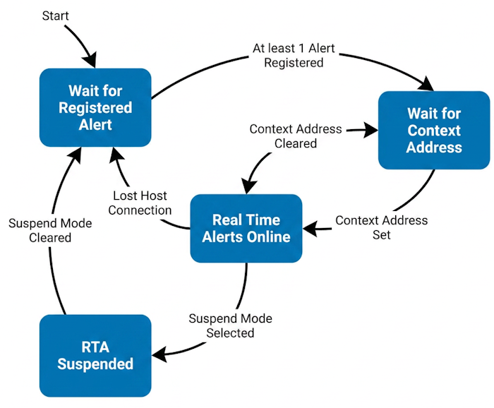 Figure 6: Real Time Alerts Feature States in a Scanner or Cradle Device
The Host system can look up the current state of the Real Time Alert feature. Note that if a device does not immediately have a Context Address, it usually resolves itself in a minute. Table 4 shows the meaning of the RTA state value returned when requested by the host.
RTA OPOS Integration (Windows)
The OPOS driver uses DirectIO commands to invoke Real-Time Alerts (RTA) methods on the scanner or cradle device and utilizes DirectIO events to receive notifications when an RTA event is triggered by the scanner. Because the Zebra OPOS Service Object automatically registers for CoreScanner notification events during the initial Open call, the host application does not need to perform manual registration to receive RTA events.
How to Execute the Direct IO Commands
Syntax
LONG DirectIO (LONG Command, LONG* pData, BSTR* pString);
Table 5: OPOS DirectIO Parameters
| Parameter | Description |
|---|---|
| Command | Command number. Represents the specific operation assigned by the Service Object. Supported RTA commands include:
|
| pData | Retrieves the CoreScanner status of the executed RTA command. This allows users to verify the execution status and identify if any errors occurred during command execution via CoreScanner. |
| pString | Input/Output string pointer. This pointer is used to bind the input XML (inXML) for the command, and it is overwritten to retrieve the output XML (outXML) sent by the CoreScanner service upon return. For more information, see the CoreScanner Methods for RTA section. |
Sample Implementation: Executing DirectIO Commands
#define DIO_RTA_GET_SUPPORTED 5500

COPOSScanner m_ctrlScanner;
LONG retVal;

CComBSTR inXML = LR"(<inArgs>
                        <scannerID>1</scannerID>
                    </inArgs>)";
LONG a = -1;

retVal = m_ctrlScanner.DirectIO(DIO_RTA_GET_SUPPORTED, &a, &inXML);
C++ MFC Sample Snippet: Handling DirectIO Events
class CSampleApp_OPOS_Scanner_Dlg : public CDialog {
protected: COPOSScanner m_ctrlScanner;
public: virtual BOOL OnInitDialog() {
    CDialog::OnInitDialog();
    m_ctrlScanner.Open("ZEBRA_SCANNER");
    m_ctrlScanner.ClaimDevice(1000);
    m_ctrlScanner.SetDeviceEnabled(TRUE);
    return TRUE;
}
void DirectIOEventScanner1(long EventNumber, long* pData, BSTR* pString) {

    if (EventNumber == 2000){
        if (pString && *pString)
        {
            std::wcout << L"RTA Event Received :: " << *pString << std::endl;
        }
    }
}

// This map connects the ActiveX control's event to handler function.
BEGIN_EVENTSINK_MAP(CSampleApp_OPOS_Scanner_Dlg, CDialog)
    ON_EVENT(CSampleApp_OPOS_Scanner_Dlg, IDC_SCANNER1, 2, DirectIOEventScanner1, VTS_I4 VTS_PI4 VTS_PBSTR)
END_EVENTSINK_MAP()
};
RTA JPOS Integration (Windows and Linux)
The JPOS driver uses DirectIO commands to invoke Real-Time Alerts (RTA) methods on the scanner or cradle device and utilizes DirectIO events to receive notifications when an RTA event is triggered by the scanner. Because the Zebra JPOS Service Object automatically registers for CoreScanner notification events during the initial Open call, the host application does not need to perform manual registration to receive RTA events.
How to Execute the Direct IO Commands
Syntax
void directIO (int command, int[] data, Object object) throws JposException;
Table 6: JPOS DirectIO Parameters
| Parameter | Description |
|---|---|
| Command | Command number. Represents the specific operation assigned by the Service Object. Supported RTA commands include:
|
| pData | Retrieves the CoreScanner status of the executed RTA command. This allows users to verify the execution status and identify if any errors occurred during command execution via CoreScanner. |
| pString | Input/Output string pointer. This pointer is used to bind the input XML (inXML) for the command, and it is overwritten to retrieve the output XML (outXML) sent by the CoreScanner service upon return. For more information, see the CoreScanner Methods for RTA section. |
Sample Implementation: Executing DirectIO Commands
public static final int  DIO_RTA_GET_SUPPORTED  = 0x157C; //5500
private int opCode =   DIO_RTA_GET_SUPPORTED  ;
private StringBuffer deviceParams = new StringBuffer();

deviceParams.append("<inArgs><scannerID>1</scannerID></inArgs>");

private int[] statusScanner =  new int[]{-1};
device.setDirectIO(opCode, statusScanner , (Object) deviceParams);
Sample Implementation: Handling DirectIO Events
Scanner scannerAll = new jpos.Scanner();
try {
    scannerAll.open(("ZebraAllScanners"));
    scannerAll.claim(1000);
    scannerAll.setDeviceEnabled(true);

    scannerAll.addDirectIOListener(new DirectIOListener() {
    @Override
    public void directIOOccurred(DirectIOEvent de) {
            System.out.println("Scanner:: DirectIO event occured");
            switch (de.getEventNumber()) {
                case 2000:
                    System.out.println("RTA event type : " + de.getEventNumber() + "   Event Data : " + ((String) de.getObject()));
                    break;
            }
        }
    });
} catch (JposException ex) {
    System.out.println("Scanner:: Exception in accessing Scanner " + ex.getMessage());
}
Demo Apps
Real Time Alerts (RTA) Using Direct I/O Commands in Zebra Scanner SDK OPOS/JPOS
The Zebra Scanner SDK OPOS/JPOS provides support for managing Real Time Alerts (RTA) on Zebra scanners using Direct I/O commands. RTA configuration is performed using the RTA Agent Utility. The OPOS sample application can be used as a reference to guide how to use the RTA Direct IO commands to monitor the RTA events. The same steps apply when using JPOS.
Sending Direct I/O Commands via OPOS Sample Application
To send Direct I/O commands using the OPOS sample application, follow the steps below:
- Connect a Zebra scanner that includes RTA-supported firmware and switch the scanner to a management-enabled host mode, such as USB-SNAPI, USB-OPOS, USB-IBM Hand-held, or USB-IBM Table-top.
- Launch the SDK OPOS Scanner sample application.
- Click Open and select the appropriate logical device.
- Click Claim to claim the device.
- Click Device Enable. (The device must be in an Enabled state to receive RTA events.)
Retrieving Supported RTA Events - DIO_RTA_GET_SUPPORTED
To determine the RTA events supported by the scanner, use the DIO_RTA_GET_SUPPORTED command:
- Select DIO_RTA_GET_SUPPORTED from the Direct I/O command list.
- Set the correct scanner ID.
- Execute the command.
The supported RTA events will be displayed in the OutXml section. Detailed explanations of these events can be found on the Supported Alerts section.
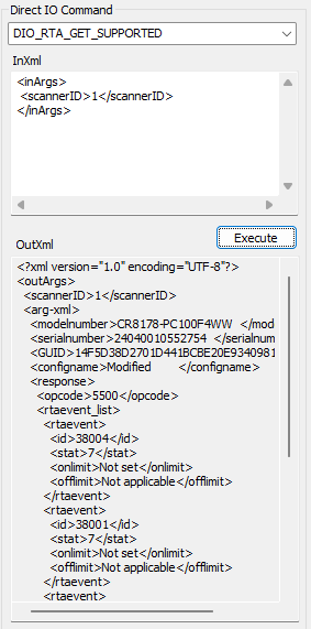 Figure 7: Supported RTA Events Returned by DIO_RTA_GET_SUPPORTED
Note: If the connected device does not support the RTA feature, the CoreScanner status will display code 117, and the Return Value and Result Code will be displayed as OPOS_E_EXTENDED.
For demonstration purposes, select the RTA attribute "Scanner out of cradle (38004)" from the Supported Alerts.
In the configuration xml in RTA Agent, values must be provided for the <id>, <stat>, and <onlimit> tags. The correct values for these tags can be determined by referring to the table’s “Attribute”, “Type”, and “Reporting Value Range” columns, which provide the necessary details for accurate configuration.
For this example, Attribute ID 38004 is selected.
The associated RTA name specifies: "Scanner is off the charger/cradle for a measured time."
The description: "The cordless scanner was removed from its charger/cradle for an extended period." Upon reviewing the Description, it becomes clearer that this event tracks the duration the cordless scanner remains out of its charger or cradle.
From the Type column, the value is identified as 7. A Type 7 value indicates that the event is designed to monitor an “above-threshold” condition, meaning the RTA event will be triggered once a specified threshold is exceeded.
The threshold is defined by setting the on-limit value, which can be determined from the “Reporting Value Range” column. For this example, the range is 5-600 minutes, allowing any value within this range to be selected. For demonstration purposes, the on-limit is set to 5 minutes.
Thus, for the RTA 38004 attribute, the configuration is established to monitor an above-threshold condition with an on-limit of 5 minutes. This means that if the scanner remains out of the cradle for more than 5 minutes, the RTA event will be triggered.
Table 7: Supported Alerts Entry for Attribute 38004
| Category | RTA Name | Attribute | Type | Reporting Value Range | Description | Reported Value(s) |
|---|---|---|---|---|---|---|
| Charging | Scanner is off of charger/cradle for a measured time | 38004 | 7 - Above Threshold | 5-600 min | The cordless scanner was removed from its charger/cradle for an extended period | Minutes off charger |
Reference: Supported Alerts.
Registering RTA Events
To use the RTA feature, the desired RTA events must be registered first. For this process, we need to use the RTA Agent Utility.
For the demonstration will use 38004 attribute. In the RTA agent configuration xml file, make sure the following attribute details are available. If not, add the following details in the <rtaevent_list> tag.
<rtaevent>
  <id>38004</id>            <-- Attribute ID
  <stat>7</stat>            <-- Type
  <onlimit>5</onlimit>      <-- Reporting Value Range
  <offlimit>Not applicable</offlimit>
</rtaevent>
Retrieving RTA Event Status - DIO_RTA_GET_EVENT_STATUS
This command retrieves the current alert status of registered RTA events.
- Select DIO_RTA_GET_EVENT_STATUS.
- Update the InXml as needed.
- Execute the command.
The response will include the status of each RTA event, indicating the following individual status:
- Registered: Indicates whether the event is currently registered.
- Reported: Indicates whether an alert has been reported for the event.
- Measuring: Indicates that the device has begun measuring the event.
- Initialized: Indicates that the device has initialized the event.
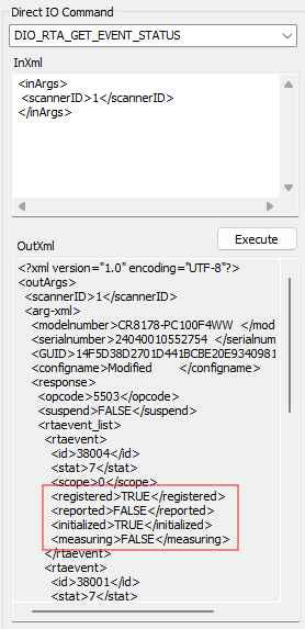 Figure 8: RTA Event Status Returned by DIO_RTA_GET_EVENT_STATUS
After successfully registering for the RTA event with ID 38004, the event will appear as Registered = TRUE and Reported = FALSE when checked using the DIO_RTA_GET_EVENT_STATUS command.
Demonstrating RTA Event Trigger (Example: Event ID 38004)
To simulate the event: Remove the scanner from the cradle and wait for 5 minutes (based on the on-limit value set to 5).
If the scanner is not returned to the cradle within this time frame, an RTA event will be triggered. Check the Log View in the OPOS sample application to verify that the RTA event was reported.
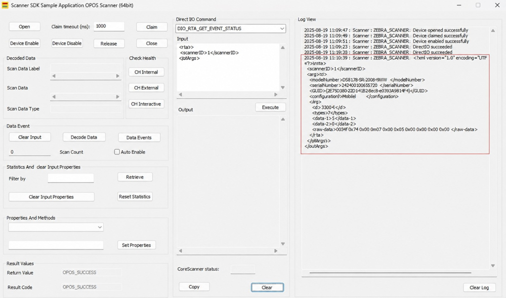 Figure 9: OPOS Sample Application Log View with a Reported RTA Event
Note: Refer to this page for detailed information on the structure and content of RTA_EVENT messages. The RTA_EVENT Message Format.
To verify the alert was triggered:
- Call DIO_RTA_GET_EVENT_STATUS again.
- The status for event ID 38004 should now show Reported = TRUE.
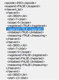 Figure 10: Event Status Showing Reported = TRUE
Resetting Event Report Status - DIO_RTA_SET_EVENT_STATUS
This command resets the Reported status of a specific RTA event back to FALSE.
- Select DIO_RTA_SET_EVENT_STATUS.
- Update the InXml with the appropriate values for:
- scannerID: The ID of the connected scanner.
- event ID: The RTA event ID to be updated.
- stat: correct stat.
- reported: Set to 0 to reset the reported flag.
- Execute the command.
To verify this:
- Call DIO_RTA_GET_EVENT_STATUS again.
- The status for event ID 38004 should now show Reported = FALSE.
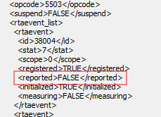 Figure 11: Event Status Showing Reported = FALSE After Reset
Suspending RTA Events - DIO_RTA_SUSPEND
This command temporarily disables triggering of RTA events.
- Select DIO_RTA_SUSPEND.
- Update the InXml with the relevant scanner ID.
- Execute the command.
<inArgs>
    <scannerID>1</scannerID>
    <cmdArgs>
        <arg-bool>true</arg-bool>
    </cmdArgs>
</inArgs>
Unregistering RTA Events - DIO_RTA_UNREGISTER
To unregister RTA events:
- Select DIO_RTA_UNREGISTER.
- Provide the scanner ID and list the event(s) to be unregistered within the <rtaevent_list> element.
- Execute the command.
Note: Multiple <rtaevent> entries can be included within the <rtaevent_list> element to unregister multiple events at once.
<inArgs>
    <scannerID>1</scannerID>
    <cmdArgs>
        <arg-xml>
            <rtaevent_list>
                <rtaevent>
                    <id>38004</id>
                    <stat>7</stat>
                </rtaevent>
            </rtaevent_list>
        </arg-xml>
    </cmdArgs>
</inArgs>
Then call DIO_RTA_GET_EVENT_STATUS. Registered set to False.
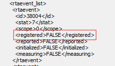 Figure 12: Event Status Showing Registered = False After Unregistering
Get Current State of RTA Events - DIO_RTA_GETSTATE
The DIO_RTA_GETSTATE command is used to query the current state of the Real Time Alert (RTA) feature on the connected scanner.
- Select DIO_RTA_SUSPEND.
- Update the InXml with the relevant scanner ID.
- Execute the command.
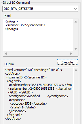 Figure 13: RTA State Returned by DIO_RTA_GETSTATE
Table 4: RTA State Values describes the possible RTA state values returned by this command.
Supported Interfaces
The Real Time Alerts feature is available for products that support the Zebra Remote Scanner Management (RSM) protocol. These RTA messages are encapsulated in the protocols of the following interfaces:
- USB SNAPI
- USB IBM Retail (Handheld/TableTop)
- USB OPOS
For the Real Time Alerts feature to work, the scanner device must be configured to operate in one of the above Host Protocols.
Supported Alerts
The following table shows all of the currently supported Real Time Alerts. The list of products that support these Alerts can be found in List of Supported Products.
Table 8: List of Supported Real Time Alerts
| Category | RTA Name | Attribute | Type | Reporting Value Range | Description | Reported Value(s) |
|---|---|---|---|---|---|---|
| Config Control | Configuration Name Tracking | 616 | 2 - Any Change | n/a | Track change of “Configuration Name” to “Modified” or “Factory Default” because of a programming barcode being scanned. | Alert Instance Count |
| Scanner Idle | Scanner Idle above threshold for x min | 38001 | 7 - Above Threshold | 5-600 min | The scanner is idle because there have been no successful decode in x min | Minutes without a decode |
| Gifted Battery | Battery charge level below minimum percentage | 30012 | 9 - Below Threshold | 1%-100% | Battery charge level has fallen below a set threshold value. | Charge Level of Battery |
| Gifted Battery | Battery charge level above maximum percentage | 30012 | 7 - Above Threshold | 1%-100% | Battery charge level has been charged above a set threshold value. | Charge Level of Battery |
| Charging | Scanner is off of charger/cradle for a measured time | 38004 | 7 - Above Threshold | 5-600 min | The cordless scanner was removed from its charger/cradle for an extended period | Minutes off charger |
| Virtual Tether | Virtual tether alarm was signaled | 38003 | 13 - Event Alarm | n/a | The scanner's Virtual Tether alarm has been activated. | Alert Instance Count |
| Scale | Scale Display Communication Error Flag | 15251 | 14 - Event Fault | n/a | The scale display is enabled but the display is not connected or there is a communication fault with the display. | Alert Instance Count |
| Scale | Scale Needs Calibration Flag | 15241 | 13 - Event Alarm | n/a | The scale's current state is that it needs calibration. | Alert Instance Count |
| Scale | Scale Communication Error Flag | 15247 | 14 - Event Fault | n/a | Communication with the scale is lost such as when the scale power cable is disconnected or there is a communications fault. | Alert Instance Count |
| Weight Guard | Weight Guard Declined Scale Reading | 38007 | 13 - Event Alarm | n/a | A scale read weight was tried and it was declined because of an unstable weight or it has an item(s) hanging over one or both edges of the scale. The state of the infrared sensors must not have "Red Calibration Health". | Alert Instance Count |
| Weight Guard | Weight Guard Communication Error Flag | 38008 | 14 - Event Fault | n/a | A communications error occurred that meets the reporting requirements of Weight Warden. The state of the infrared sensors must not have "Red Calibration Health". | Alert Instance Count, and Reporting Sensors |
| Weight Guard | Weight Guard Infrared Red Health Status | 38009 | 14 - Event Fault | n/a | An alert is sent if the Data Health of either IR sensor reaches the Red health level. | Alert Instance Count, and Reporting Sensors |
| Weight Guard | Weight Guard Infrared Orange Health Status | 38010 | 13 - Event Alarm | n/a | An alert is sent if the Data Health of either IR sensor reaches the Orange health level. | Alert Instance Count, and Reporting Sensors |
| Electronic Article Surveillance | Sensormatic EAS Device Detach | 38015 | 13 - Event Alarm | n/a | An alert is sent if a scanner EAS device is detached. | Alert Instance Count |
Product Support Matrix
Table 9: List of Supported Products
| Category | RTA Name | Attribute | Type | MP7200 | MP7 | SP7200 | DS8108/DS8208 | CR8178/CR8288 | DS8178/DS8288 |
|---|---|---|---|---|---|---|---|---|---|
| Config Control | Config File Name Tracking | 616 | 2 - Any Change | X | X | X | X | X | |
| Scanner Idle | Scanner Idle above threshold for x min | 38001 | 7 - Above Threshold | X | X | X | X | ||
| Gifted Battery | Battery charge level below minimum percentage | 30012 | 9 - Below Threshold | X | |||||
| Gifted Battery | Battery charge level above maximum percentage | 30012 | 7 - Above Threshold | X | |||||
| Charging | Scanner is off charger/cradle for a measured time | 38004 | 7 - Above Threshold | X | |||||
| Virtual Tether | Virtual tether alarm was signaled | 38003 | 13 - Event Alarm | X | |||||
| Scale | Scale Display Communication Error Flag | 15251 | 14 - Event Fault | X | X | ||||
| Scale | Scale Needs Calibration Flag | 15241 | 13 - Event Alarm | X | X | ||||
| Scale | Scale Communication Error Flag | 15247 | 14 - Event Fault | X | X | ||||
| Weight Guard | Weight Guard Declined Scale Reading | 38007 | 13 - Event Alarm | X | |||||
| Weight Guard | Weight Guard Communication Error Flag | 38008 | 14 - Event Fault | X | |||||
| Weight Guard | Weight Guard Infrared Red Health Status | 38009 | 14 - Event Fault | X | |||||
| Weight Guard | Weight Guard Infrared Orange Health Status | 38010 | 13 - Event Alarm | X | |||||
| Electronic Article Surveillance | Sensormatic EAS Device Detach | 38015 | 13 - Event Alarm | X |
Wireless Scanner Product Alerts
Gifted Battery Percentage Below Minimum (Attribute 30012/Type 9)
This alert monitors the current battery charge level on a wireless scanner. If it reaches or goes below the On-Limit value, then an alert is sent. Once the alert is on, if the scanner is charged to the Off-Limit value, then the alert is turned off. The system is then ready to monitor this alert again.
NOTES:
- When this alert is sent, the first value reported is the current battery charging level.
- The second reported data value is 0 for this alert.
- The On-Limit must be lower than the Off-Limit. If not, the values are swapped.
- The On-Limit and Off-Limit values have an accuracy of 1 percent and they must be within the range of 1 to 100.
- Both the On-Limit and Off-Limit value settings must be configured for the “Measuring” status to be set. Otherwise, the “Measuring” status is cleared at initialization.
- If either the On-Limit or Off-Limit is set greater than 100, it is automatically reset to 100.
- If either the On-Limit or Off-Limit is set to zero, it is automatically reset to 1.
- If the On-Limit and Off-Limit values are set equal, and the On-Limit is greater than 1, then the On-Limit is automatically decreased by 1.
- If the On-Limit is greater than the Off-Limit, the two settings are swapped.
Gifted Battery Percentage Above Maximum (Attribute 30012/Type 7)
This alert monitors the current battery charge level on a wireless scanner. If it reaches or goes above the On-Limit value, then an alert is sent. Once the alert is on, if the battery discharges and reaches below the Off-Limit value, then the alert is turned off. The system is then ready to monitor this alert again.
NOTES:
- When this alert is sent, the first reported value is the current battery charging level.
- The second reported data value is 0 for this alert.
- The On-Limit must be greater than the Off-Limit. If not, the values are automatically swapped.
- The On-Limit and Off-Limits have an accuracy of 1 percent and they must be within the range of 1 to 100.
- Both the On-Limit and Off-Limit value settings must be configured for the “Measuring” status to be set. Otherwise, the “Measuring” status is cleared at initialization.
- When either the On-Limit or Off-Limit value specified is set greater than 100, it is automatically reset to 100.
- When either the On-Limit or Off-Limit is set to zero, it is automatically reset to 1.
- If the On-Limit and Off-Limit values are set equal, and the Off-Limit is less than 100, then the Off-Limit is automatically incremented by 1.
- If the On-Limit is set less than the Off-Limit, the two settings are automatically swapped.
Wireless Cradle Product Alerts
RTA Scanner out of Cradle/ Value Above Maximum (Attribute 38004/Type 7)
This alert watches the wireless scanner's cradle insertion status. If the scanner is removed from the cradle more than the number of minutes specified on the On-Limit, then an alert is sent. Once the alert is on, if the scanner is inserted into the cradle, then the alert is turned off. The system is then ready to monitor this alert again.
NOTES:
- When this alert is sent, the first data value reported is the number of minutes out of the cradle.
- The second reported data value is 0 for this alert.
- The On-Limit value has an accuracy of 1 minute and it must be within the range of 5 to 600 minutes.
- When the On-Limit is set below 5, then it is automatically reset to 5.
- When the On-Limit is set above 600, then it is automatically reset to 600.
- The scanner must be in the cradle for the “Measuring” status to be set.
- When the scanner is removed from the cradle, the “Measuring” status and the “Reported” status is cleared.
- When the “Measuring” status is cleared, the alert's “Reporting” status is also cleared.
- The “Measuring” status must be set for the alert to be monitored and reported.
RTA Virtual Tether Alert/ Event Alarm (Attribute 38003/Type 13)
This alert monitors the Virtual Tether feature status. If the feature is enabled on the cradle, and an out-of-range alarm was sounded, then an alert is sent. Once the alert is on, if the alert is cancelled or stopped, then the alert is turned off. The system is ready to monitor this alert again.
NOTES:
- When this alert is sent, the current Alert Count is the first reported data value.
- The second reported data value is 0 for this alert.
- There are no settings for this alert. If any setting values are sent, they are ignored.
- When an alert is sent, the temporary loss of host connection shall not cause the RTA settings to be cleared.
Flatbed Scanner Product Alerts
Stats Scale Display Comm Error Flag/ Event Fault (Attribute 15251/Type 14)
This alert monitors for a Display Communication Error statistic being reported. If there is a communication error reported, then an alert is sent. Once the alert is on, if the display communication error no longer exists then the alert is turned off. The system is ready to monitor this alert again.
NOTES:
- When this alert is sent, the current Alert Count is the first reported data value.
- The second reported data value is 0 for this alert.
- There are no settings for this alert. If any setting values are sent, they are ignored.
- Both the Scale Display Configuration (#986) and Scale Enable (#1197) parameters must be enabled for the “Measuring” status to be set. Otherwise, the “Measuring” status is cleared.
- When the “Measuring” status is cleared, the alert's “Reporting” status is also cleared.
- The “Measuring” status must be set for the Alert to be monitored and reported.
Stats Scale Needs to be Calibrated Flag/ Event Alarm (Attribute 15241/Type 13)
This alert monitors for the Scale Calibration statistic to be reported as False. If there is a need for calibration, an alert is sent. When the calibration process is completed, the scanner is restarted. This will cause the RTA component to restart. So, following Calibration of the scale, all alerts are unregistered.
NOTES:
- When this alert is sent, the current Alert Count is reported. This count will reset to 0 when Calibration is performed.
- The supplementary data is 0 for this alert
- There are no settings for this alert. If any setting value is sent, they are ignored.
RTA Weight Guard Declined Scale Request/ Event Alarm (Attribute 38007/Type 13)
This alert monitors for when a Read Weight request is made and is declined because the Weight Guard software detected a Beam Break. When this occurs, an alert is sent. Once the alert is on, if a non-zero Read Weight request is successfully made, then the alert is turned off. The system is ready to monitor this alert again.
NOTES:
- When this alert is sent, the current Alert Count is the first reported data value.
- The second reported data value is 0 for this alert.
- There are no settings for this alert. If any setting values are sent, they are ignored.
- Both the Weight Guard Enable (#2427) and Scale Enable (#1197) parameters must be enabled for the “Measuring” status to be set. Otherwise, the “Measuring” status is cleared.
- When the “Measuring” status is cleared, the alert's “Reporting” status is also cleared.
- The “Measuring” status must be set for the Alert to be monitored and reported.
RTA Weight Guard IR Sensor Red Health/ Event Fault (Attribute 38009/Type 14)
This alert monitors the Weight Guard subsystem to report a Red health level over UIF (Red LED) and also checks if one or both IR sensors report the Red health status. If this occurs, an alert is sent. Once the alert is on, if the Red LED UIF indication is cancelled, and both IR sensors no longer have the Red Health status, then the alert is turned off. The system is then ready to monitor this alert again.
NOTES:
- When this alert is sent, the current Alert Count is the first reported data value.
- The second reported data value is the current states of the A and B IR sensors: 1 = Sensor A is Red, 2 = Sensor B is Red, 3 = Both Sensors are Red.
- There are no settings for this alert. If any setting values are sent, they are ignored.
- Both the Weight Guard Enable (#2427) and Scale Enable (#1197) parameters must be enabled for the “Measuring” status to be set. Otherwise, the “Measuring” status is cleared.
- When the “Measuring” status is cleared, the alert's “Reporting” status is also cleared.
- The “Measuring” status must be set for the Alert to be monitored and reported.
RTA Weight Guard IR Sensor Orange Health/ Event Alarm (Attribute 38010/Type 13)
This alert monitors if the Weight Guard subsystem reports a message that one or both of the IR sensors have the Orange health status. When this occurs, an alert is sent. Once the alert is on, if both IR sensors no longer have the Orange Health status, then the alert is turned off. The system is then ready to monitor this alert again.
NOTES:
- When this alert is sent, the current Alert Count is the first reported data value.
- The second reported data value is the current states of the A and B IR sensors: 1 = Sensor A is Orange, 2 = Sensor B is Orange, 3 - Both Sensors are Orange.
- There are no settings for this alert. If any setting values are sent, they are ignored.
- Both the Weight Guard Enable (#2427) and Scale Enable (#1197) parameters must be enabled for the “Measuring” status to be set. Otherwise, the “Measuring” status is cleared.
- When the “Measuring” status is cleared, the alert's “Reporting” status is also cleared.
- The “Measuring” status must be set for the Alert to be monitored and reported.
RTA Weight Guard Communication Error Flag/ Event Fault (Attribute 38008/Type 14)
This alert monitors if the Weight Guard subsystem reports a communication error. When this occurs, n alert is sent. Once the alert is on, if Weight Guard reports no communication error, then the alert is turned off. The system is then ready to monitor this alert again.
NOTES:
- When this alert is sent, the current Alert Count is the first reported data value.
- The second reported data value is 0 for this alert.
- There are no settings for this alert. If any setting values are sent, they are ignored.
- Both the Weight Guard Enable (#2427) and Scale Enable (#1197) parameters must be enabled for the “Measuring” status to be set. Otherwise, the “Measuring” status is cleared.
- When the “Measuring” status is cleared, the alert's “Reporting” status is also cleared.
- The “Measuring” status must be set for the Alert to be monitored and reported.
Stats Scale Communication Error Flag/ Event Fault (Attribute 15247/Type 14)
This alert monitors the scale's UART driver for a communication error. When this occurs, an alert is sent. Once the alert is on, if the communication rrror is cleared, the alert is turned off. The system is rhen ready to monitor this alert again.
Notes:
- When this alert is sent, the current Alert Count is the first reported data value.
- The second reported data value is 0 for this alert.
- There are no settings for this alert. If any setting values are sent, they are ignored.
- The Scale Enable (#1197) parameter must be enabled for the “Measuring” status to be set. Otherwise, the “Measuring” status is cleared.
- When the “Measuring” status is cleared, the alert's “Reporting” status is also cleared.
- The “Measuring” status must be set for the Alert to be monitored and reported.
RTA Sensormatic EAS Detach/ Event Alarm (Attribute 38015/Type 13)
This alert monitors communication with the Sensormatic external device. When in the Measuring state, the alert code will monitor the current status of the external Sensormatic device. If the Sensormatic device is found to be unresponsive or unattached, an alert is sent. Once the alert is on, if the Sensormatic external device is communicating, the alert is turned off. The system is then ready to monitor this alert again.
Notes:
- When this alert is sent, the current Alert Count is the first reported data value.
- The second reported data value is 0 for this alert.
- There are no settings for this alert. If any setting values are sent, they are ignored.
- This alert enters the measuring state when a Sensormatic EAS operating mode (Parameter #977) is enabled:
- Sensormatic Auto Mode (0)
- Sensormatic Always Enable Deactivation Mode (1)
- Sensormatic Barcode Interlock Mode (2)
- Sensormatic Barcode Auto Interlock Mode (3)
- Sensormatic Self Service Mode (4)
- Sensormatic Scan Enable Interlock Mode (5)
- If any other EAS Operating mode is selected, the “Measuring” status and the “Reported” status are cleared.
- An alert is raised when there is a communication error with the external Sensormatic device.
- An alert is raised when there is no response to a “Check Connection”.
- This alert ends when a command is processed by the external EAS device.
- This alert ends when a message is received from the external EAS device.
All Product (including Corded Scanner) Alerts
RTA Scanner Idle/ Value Above Maximum (Attribute 38001/Type 7)
This alert monitors the timing between successful decodes. If the scanner (the attached wireless scanner) does not have a successful decode in a time interval more than the number of minutes specified on the On-Limit, an alert is sent. Once the alert is on, if the scanner successfully decodes a barcode, the alert is turned off. The system is then ready to monitor this alert again.
Notes:
- When this alert is sent, the first reported data value s the number of minutes since the last successful decode.
- The second reported data value is 0 for this alert.
- The On-Limit has an accuracy of 1 minute and must be within the range of 5 to 600 minutes.
- If the On-Limit is set below 5, it is automatically reset to 5.
- If the On-Limit is set above 600, it is automatically reset to 600.
Configuration Name/ Event Alarm (Attribute 616/Type 13)
This alert monitors the value of the scanner device's last loaded Configuration Name. If the Configuration Name (#616) is changed to “Modified” or “Factory Defaults”, an alert is sent. Once the alert is on, if the Configuration Name is updated to a string other than “Modified” or “Factory Defaults”, the alert is turned off. The system is then ready to monitor this alert again.
Notes:
- When this alert is sent, the first reported data value is the current AlertCount.
- The second reported data value is 0 for this alert.
- There are no settings for this alert. If any setting values are sent, they are ignored.